Motherboard
The motherboard
is a big circuit board inside your computer. The motherboard contains the
connectors for attaching devices to your computer. These devices can range from
a mouse to a modem to memory.
The motherboard
acts as the central nervous system for a computer, transmitting information back
and forth between the brain of the computer (CPU) and various parts (components
and peripherals). Every individual piece of a computer connects to the
motherboard in one way or another.
A motherboard can also be called a main board, a system board or a
planar boards.
“Think of a motherboard as a scale model of a futuristic city
with many modular plug-in buildings, each using power from a common electrical
system. Multiple-lane highways of various widths transport data between the
buildings. The motherboard is the data and power infrastructure for the entire
computer.” (Taken from www.howthingswork.com)
A motherboard
is a multi-layered printed circuit board. Copper circuit paths called traces
that resemble a complicated roadmap carry signals and voltages across the motherboard.
A motherboard has many different slots, chips and pins on it. Let’s
discuss what some of the more common ones are.
There are many different form factors (styles) of motherboards.
The main form factor in use today is the ATX form factor motherboard. Depending
on the form factor of a motherboard you may have different capabilities
or different types of connectors.
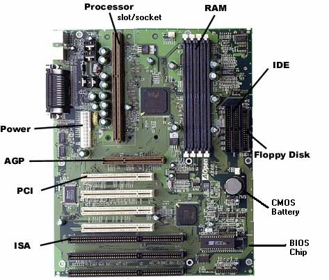
Motherboard
The
Processor Slot/Socket
This is where the processor sits in the computer. It plugs
into the motherboard. We will discuss the function of the processor more in
depth later. There are two types of processor connections found on motherboards.
They will be slotted or socketted .This means that the type of connector on the
motherboard must match the type of processor that you put in. There are also
different types of socketted and slotted processor slots. The amount of
connectors or pin slots varies between types.
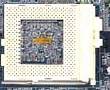
Socketted Processor
Connector
Slotted Processor Connector
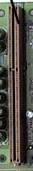
RAM
Slots
These are also
slots on the motherboard. These are used to connect memory to the motherboard.
These slots will usually be black in color and have some form of push tabs on
the end for releasing the memory module that have been inserted. The numbers of
memory slots on a motherboard vary depending on the type of motherboard. There
is never just one memory slot on a motherboard and the memory slots always run
parallel to each other.
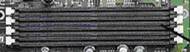
Ram
Slots
IDE
Connectors
These are the
connectors for any IDE devices that you put into your computer. Common IDE
devices are Hard Drives and CD-ROM drives. There are two of these IDE connectors
on a motherboard. They are called the Primary IDE Connector (for main devices)
and the Secondary IDE Connector (for secondary, less important devices). If you
look very closely on the motherboard you will find tiny labels for each of these
connectors so that you know which one is the primary and which one is the
secondary. You plug the IDE cables for your IDE hardware into these connectors.
Today these slots are ‘keyed’. When you plug an IDE cable into a connector
there is a certain way that it should be plugged in. Keyed means that there is a
way to tell which way to do this. There are two mains methods of keying a
connector or it’s cable. The first is to put a lip on the cable that plugs
into an opening on the side of the connector (figure 3) and the second way is to
fill in a spot where a pin would usually be. (figure 4). Keying helps to make
sure that your cables are plugged in properly and that the devices they connect
to function. If there is no keying method used for the connector and the cable
there is always one last way to find out.
Floppy
Connector
There is one
floppy connector on most motherboards. The floppy connector will be near the IDE
connectors on most motherboards and is a bit shorter than an IDE connector. You
plug the floppy cable that comes from your floppy drive into this connector so
that it can be used by the computer.
CMOS
Battery
The CMOS battery
looks like a big watch battery. It is 3 volts. The job of the CMOS battery is to
supply enough power to your computer that when it is turned off it can still
store low level information for your computer. An example of this information is
the date and time on your computer. Each time you turn your computer on the date
and time is correct, even if the computer has been off for a couple days. These
batteries do not last forever and if you notice that you start to lose time on
your computer it is time to replace the CMOS battery.
BIOS
Chip
BIOS stands for
Basic Input Output System. The BIOS is built-in software that determines what a
computer can and cannot do. The BIOS contains all the code required to control
hardware devices in your computer. The BIOS chips is the physical location where
the BIOS setup program is stored. This allows the BIOS to still function even if
other hardware components may not. We will discuss the BIOS more in depth later.
ISA
ISA is a connector
or bus for ISA type expansion cards. A bus is the channel or path between the
components in a computer. There are many types of buses. ISA is just one of
them. ISA connectors are an older type of bus. Most current motherboards will no
longer have ISA slots on them. ISA slots are usually black in color, appear
along the bottom of the motherboard and are the longest of expansion slots on
the motherboard.
PCI
PCI is a newer bus
and the most current for the majority of expansion cards. Most motherboards have
multiple (from 3 – 6) PCI slots on them. PCI slots are usually beige in color
and appear above the ISA slots on a motherboard or if there are no ISA slots,
along the bottom of the motherboard. PCI and ISA buses connect to the
motherboard through a bridge.
AGP
Accelerated
Graphics
Port.
This is the newest type expansion card connector on motherboards today.
This connector is used for dedicated video and can only support AGP video cards.
AGP supports faster performance and direct access to system memory.
Power
Connector
The power
connector on the motherboard is used to plug the power supply into the
motherboard in order to provide power for expansion cards, memory and
processors. The power connector is a 20 pin connector.
Motherboard
Specifications
Motherboards have various different specifications. Some
specifications you might hear are;
-
Number of slots and what type
-
Number of I/O connectors and
what type
-
Supported memory and processor
-
Bus speeds
Motherboard
Problems
Some problems that
you may experience with motherboards are non-functional expansion slots,
processor sockets, IDE connectors and memory sockets. When these areas of a
motherboard become non-functional the devices hooked to or plugged into them
will no longer work.
There are also
problems when buses or chipsets on the motherboard stop working. These problems
will usually render parts or all of your motherboard non-functional.
Some motherboards
require jumper settings. Jumpers are small plastic covers that fit onto pins on
the motherboard. Based on how these jumpers are put on, different settings can
be achieved. Incorrect jumper settings can cause a motherboard to stop working
temporarily or permanently.
Motherboard
Troubleshooting
Motherboards are
usually the last device to be suspected of causing any hardware problems. Most
troubleshooting will start with the problem device.
Some motherboards
may emit a series of beeps, called a beep code. This code can be researched on
the Internet to find out what the issue may be. Motherboards may also have a
small light on them called an LED. The color of this LED can also be used to
determine where an issue lies. These LED codes can be researched on the Internet
using the manufacturers’ website.
Knowledge
Check #2
Match
the components on the left to their description on the right.
| AGP
Connector |
Black
slots with push tabs |
| RAM
Slots |
Built-in
software |
| IDE
Connector |
Slot
used for a video card |
| BIOS
Chip |
Used
to hook-up a hard drive |
Please
include your answer to this question in the email that you started previously.
Click
on the blue arrow to continue
Return
to Table of Contents